Dfi BT160 Manuel d'utilisateur
Naviguer en ligne ou télécharger Manuel d'utilisateur pour Carte mère Dfi BT160. DFI BT160 User Manual Manuel d'utilisatio
- Page / 71
- Table des matières
- MARQUE LIVRES
Noté. / 5. Basé sur avis des utilisateurs
- BT160/161 1
- Copyright 2
- Trademarks 2
- Table of Contents 3
- About this Manual 4
- Warranty 4
- Safety Measures 4
- About the Package 5
- Optional Items 5
- Before Using the System Board 5
- Chapter 1 - Introduction 6
- Chapter 1 6
- Chapter 2 10
- Jumper Settings 13
- Rear Panel I/O Ports 21
- I/O Connectors 24
- Chapter 3 - BIOS Setup 32
- Chapter 3 32
- Select Screen 36
- Select Item 36
- Select Screen 49
- Notice: BIOS SPI ROM 51
- Chapter 4 52
- Chapter 5 65
- Register Description 65
- Function Description 66
- Sample Code 66
- Appendix A 67
- Appendix B 68
- Appendix C 70
Résumé du contenu
Page 1 - BT160/161
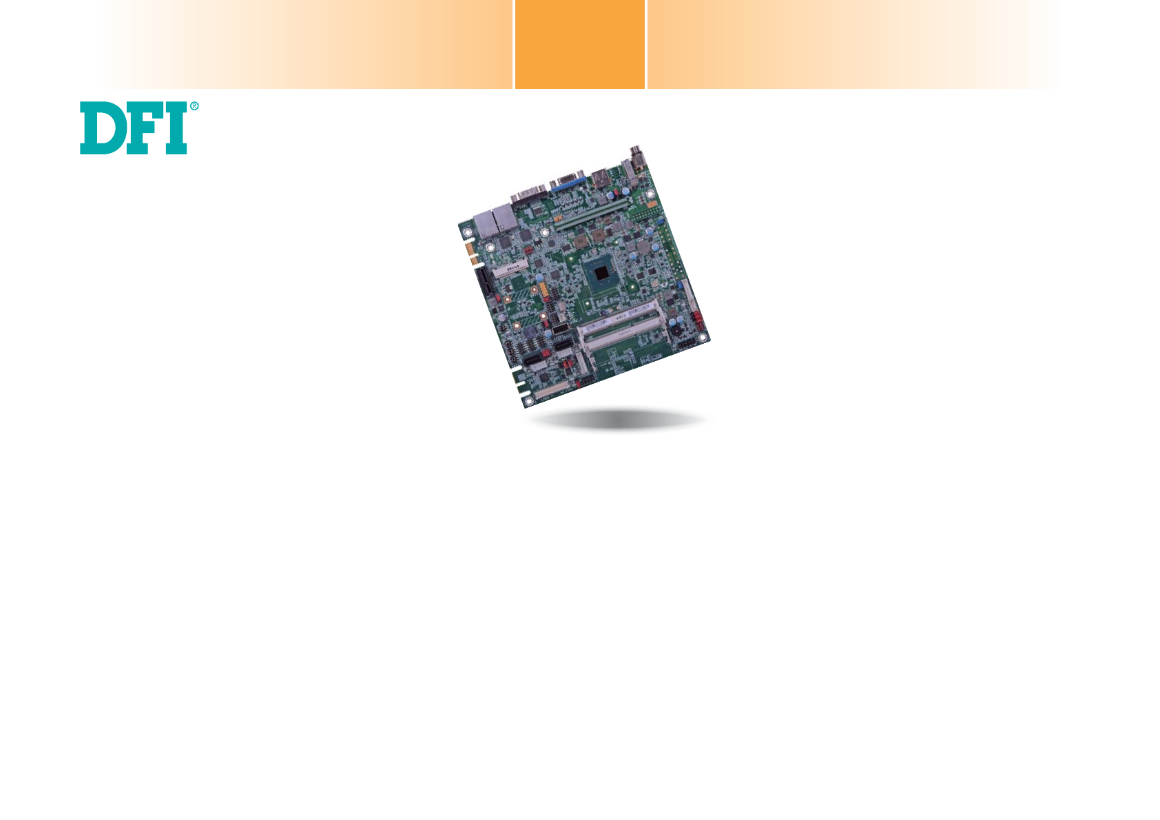
1BT160/161Mini-ITX Industrial MotherboardUser’s ManualA31610524
Page 2 - Trademarks
www.d.com10Chapter 2 Hardware InstallationChapter 2The system board supports the following memory interface. Single Channel (SC)Data will be accessed
Page 3 - Table of Contents
www.dfi .com11Chapter 2 Hardware InstallationChapter 2Installing the DIMM Module1. Make sure the PC and all other peripheral devices connected to it
Page 4 - Safety Measures
www.dfi .com12Chapter 2 Hardware InstallationChapter 2Installing the Fan and Heat SinkThe CPU must be kept cool by using a CPU fan with heat sink. With
Page 5 - Before Using the System Board
www.dfi .com13Chapter 2 Hardware InstallationChapter 2Jumper SettingsClear CMOS DataIf you encounter that CMOS data becomes corrupted, you can reconfig
Page 6 - Chapter 1
www.dfi .com14Chapter 2 Hardware InstallationChapter 2JP5, JP7 and JP14 are used to select the power of the USB ports. Selecting +5V_standby will allow
Page 7
www.dfi .com15Chapter 2 Hardware InstallationChapter 2COM 4 RS232/422/485 SelectJP22, JP23 and JP25 are used to configure the COM port 4 to RS232, RS42
Page 8
www.dfi .com16Chapter 2 Hardware InstallationChapter 2Mini PCIe/mSATA Signal SelectJP9 is used to select the Mini PCIe signal: PCIe or mSATA (optional)
Page 9
www.dfi .com17Chapter 2 Hardware InstallationChapter 2Mini PCIe/mSATA Power SelectJP6 allows you to select the power rail for the Mini PCIe or mSATA de
Page 10 - Chapter 2
www.dfi .com18Chapter 2 Hardware InstallationChapter 2Backlight Power Select1321321-2 On: +5V2-3 On: +3.3V (default)JP16 is used to select the power le
Page 11
www.dfi .com19Chapter 2 Hardware InstallationChapter 2SATA DOM Power Select1-2 On: GND (default)2-3 On: +5V 132132Note:1. SATA port 0 provides adequate
Page 12
2CopyrightThis publication contains information that is protected by copyright. No part of it may be re-produced in any form or by any means or used t
Page 13 - Jumper Settings
www.dfi .com20Chapter 2 Hardware InstallationChapter 2Digital I/O Output StateBased on the power level of DIO (Digital I/O) selected on JP17, JP20 (DIO
Page 14
www.dfi .com21Chapter 2 Hardware InstallationChapter 2Rear Panel I/O PortsThe rear panel I/O ports consist of the following:• 1 12V DC-in jack (defaul
Page 15
www.dfi .com22Chapter 2 Hardware InstallationChapter 2COM (Serial) PortsCOM 1: RS232COM 2COM 3129DCD-TDGNDRTS-RI-RDDTR-DSR-CTS-COM 4COM 2 and COM 3: RS
Page 16
www.dfi .com23Chapter 2 Hardware InstallationChapter 2RJ45 LAN Ports LAN 1Features• 2 Intel® I210 PCI Express Gigabit Ethernet controllersThe LAN ports
Page 17
www.dfi .com24Chapter 2 Hardware InstallationChapter 2Wake-On-USB Keyboard/MouseThe Wake-On-USB Keyboard/Mouse function allows you to use a USB keyboar
Page 18
www.dfi .com25Chapter 2 Hardware InstallationChapter 2SATA (Serial ATA) Connectors7RXNGNDTXPTXNGND1RXPGND• 2 Serial ATA 2.0 ports - SATA 0 and SAT
Page 19
www.dfi .com26Chapter 2 Hardware InstallationChapter 2Chassis Intrusion Connector The board supports the chassis intrusion detection function. Connect
Page 20
www.dfi .com27Chapter 2 Hardware InstallationChapter 2LVDS LCD Panel ConnectorLCD/Inverter Power ConnectorThe system board allows you to connect a LCD
Page 21 - Rear Panel I/O Ports
www.dfi .com28Chapter 2 Hardware InstallationChapter 2Cooling Fan ConnectorsThe fan connectors are used to connect cooling fans. The cooling fans will
Page 22
www.dfi .com29Chapter 2 Hardware InstallationChapter 2ATX Power Connector - BT160Use a power supply that complies with the ATX12V Power Supply Design G
Page 23
3Copyright ...2Trademarks ...
Page 24 - I/O Connectors
www.dfi .com30Chapter 2 Hardware InstallationChapter 2DFI Proprietary Extension BusPins Pin Assignment Pins Pin AssignmentA1GNDB1+12VA2+12VB2+12VA3+12V
Page 25
www.dfi .com31Chapter 2 Hardware InstallationChapter 2BatteryBatteryStandby Power LEDThis LED will light red when the system is in the standby mode. It
Page 26
www.dfi .com32Chapter 3 BIOS SetupChapter 3Chapter 3 - BIOS SetupOverview The BIOS is a program that takes care of the basic level of communication bet
Page 27
www.dfi .com33Chapter 3 BIOS SetupChapter 3MainThe Main menu is the first screen that you will see when you enter the BIOS Setup Utility. System DateTh
Page 28
www.dfi .com34Chapter 3 BIOS SetupChapter 3Enable or Disable Serial Port (COM)Aptio Setup Utility - Copyright (C) 2013 American Megatrends, Inc.Version
Page 29
www.dfi .com35Chapter 3 BIOS SetupChapter 3Enable or Disable Serial Port (COM)Aptio Setup Utility - Copyright (C) 2013 American Megatrends, Inc.Version
Page 30
www.dfi .com36Chapter 3 BIOS SetupChapter 3Serial Port Enable or disable the serial COM port. Change SettingsSelect the IO/IRQ settings for the sup
Page 31
www.dfi .com37Chapter 3 BIOS SetupChapter 3HW MonitorThis section is used to monitor the hardware status.Aptio Setup Utility - Copyright (C) 2013 Ameri
Page 32 - Chapter 3
www.dfi .com38Chapter 3 BIOS SetupChapter 3CPU ConfigurationThis section is used to configure the CPU. It will also display the detected CPU informatio
Page 33
www.dfi .com39Chapter 3 BIOS SetupChapter 3Network Stack ConfigurationThis section is used to enable or disable network stack settings.Enable/Disable U
Page 34
4About this ManualAn electronic file of this manual is included in the CD. To view the user’s manual in the CD, in-sert the CD into a CD-ROM drive. Th
Page 35
www.dfi .com40Chapter 3 BIOS SetupChapter 3Security Device SupportThis field is used to enable or disable BIOS supporting for the security device. O.S
Page 36 - Select Item
www.dfi .com41Chapter 3 BIOS SetupChapter 3USB ConfigurationThis section is used to configure the parameters of USB device.Enables Legacy USB support.
Page 37
www.dfi .com42Chapter 3 BIOS SetupChapter 3Intel(R) I210 Gigabit Network Connection - 00:01:29:51...This section is used to configure the parameters of
Page 38
www.dfi .com43Chapter 3 BIOS SetupChapter 3Intel(R) I210 Gigabit Network Connection - 00:01:29:51...This section is used to configure the parameters of
Page 39
www.dfi .com44Chapter 3 BIOS SetupChapter 3ChipsetThis section configures relevant chipset functions.Aptio Setup Utility - Copyright (C) 2013 American
Page 40
www.dfi .com45Chapter 3 BIOS SetupChapter 3Intel IGD ConfigurationAptio Setup Utility - Copyright (C) 2013 American Megatrends, Inc.Version 2.16.1242.
Page 41
www.dfi .com46Chapter 3 BIOS SetupChapter 3 LCD Panel Type Select the LCD panel used by Internal Graphics Device by selecting the appropriate
Page 42
www.dfi .com47Chapter 3 BIOS SetupChapter 3Azalia HD Audio OptionsAptio Setup Utility - Copyright (C) 2013 American Megatrends, Inc.Version 2.16.1242.
Page 43
www.dfi .com48Chapter 3 BIOS SetupChapter 3Aptio Setup Utility - Copyright (C) 2013 American Megatrends, Inc.Version 2.16.1242. Copyright (C) 2013 Amer
Page 44
www.dfi .com49Chapter 3 BIOS SetupChapter 3BootNumber of seconds to wait for setup activation key.65535(0xFFFF) means indefi nite waiting. Version 2.16.
Page 45
5About the PackageThe package contains the following items. If any of these items are missing or damaged, please contact your dealer or sales represen
Page 46
www.dfi .com50Chapter 3 BIOS SetupChapter 3Updating the BIOSTo update the BIOS, you will need the new BIOS file and a flash utility, AFUDOS.EXE. Please
Page 47
www.dfi .com51Chapter 3 BIOS SetupChapter 3Notice: BIOS SPI ROM1. The Intel® Management Engine has already been integrated into this system board. Due
Page 48
www.dfi .com52Chapter 4 Supported SoftwareChapter 4Chapter 4 - Supported SoftwareThe CD that came with the system board contains drivers, utilities and
Page 49 - Select Screen
www.dfi .com53Chapter 4 Supported SoftwareChapter 4Intel Chipset Software Installation UtilityThe Intel Chipset Device Software is used for updating Wi
Page 50
www.dfi .com54Chapter 4 Supported SoftwareChapter 4Intel HD Graphics DriversTo install the driver, click “Intel HD Graphics Drivers” on the main menu.1
Page 51 - Notice: BIOS SPI ROM
www.dfi .com55Chapter 4 Supported SoftwareChapter 4Intel LAN DriversTo install the driver, click “Intel LAN Drivers” on the main menu. 1. Setup is rea
Page 52 - Chapter 4
www.dfi .com56Chapter 4 Supported SoftwareChapter 4Kernel Mode Driver Framework (For Windows 7 only)To install the driver, click “Kernel Mode Driver Fr
Page 53
www.dfi .com57Chapter 4 Supported SoftwareChapter 43. The step displays the installing status in the progress.4. Click “Finish“ when the installation i
Page 54
www.dfi .com58Chapter 4 Supported SoftwareChapter 4Intel Sideband Fabric Device (MBI) Driver(For Windows 8.x only)To install the driver, click “Intel S
Page 55
www.dfi .com59Chapter 4 Supported SoftwareChapter 4HW UtilityHW Utility provides information about the board, HW Health, Watchdog, DIO, and Backlight.
Page 56
6Rear Panel I/O Ports• 1 12V DC-in jack (default) or 4-pin power connector* (optional) - BT161• 1 DB-9 RS232 serial port • 1 DB-15 VGA port• 2 RJ45 LA
Page 57
www.dfi .com60Chapter 4 Supported SoftwareChapter 4The HW Utility icon will appear on the desktop. Double-click the icon to open the utility.Informatio
Page 58
www.dfi .com61Chapter 4 Supported SoftwareChapter 4DIODIO2Backlight
Page 59
www.dfi .com62Chapter 4 Supported SoftwareChapter 4Infineon TPM Driver and Tool (option)To install the driver, click “Infineon TPM driver and tool (opt
Page 60
www.dfi .com63Chapter 4 Supported SoftwareChapter 47. After the installation completed, click Finish.8. Click “Yes“ to restart your system.Intel USB 3.
Page 61
www.dfi .com64Chapter 4 Supported SoftwareChapter 4Adobe Acrobat Reader 9.3To install the reader, click “Adobe Acrobat Reader 9.3” on the main menu.1.
Page 62
www.dfi .com65Chapter 5 Digital I/O Programming GuideChapter 5Chapter 5 - Digital I/O Programming GuideRegister DescriptionThe Input Port Register (reg
Page 63
www.dfi .com66Chapter 5 Digital I/O Programming GuideChapter 5Function DescriptionI2CWriteByte(SlaveAddr, SubAddr, Data): Write a Byte data to a specif
Page 64
www.dfi .com67Appendix A Watchdog Sample CodeAppendix AAppendix A - Watchdog Sample Code;Software programming example:;--------------------------------
Page 65 - Register Description
www.dfi .com68Appendix B System Error MessageAppendix BAppendix B - System Error MessageWhen the BIOS encounters an error that requires the user to cor
Page 66 - Sample Code
www.dfi .com69Appendix B System Error MessageAppendix BDXE Phase CodesıŹĺijġ ġ őńŊġŃŶŴġŪůŪŵŪŢŭŪŻŢŵŪŰůġŪŴġŴŵŢųŵŦťġ ġıŹĺĴġ ġ őńŊġŃŶŴġʼnŰŵġőŭŶŨġńŰůŵųŰŭŭŦųġŊ
Page 67 - Appendix A
7Chapter 1Chapter 1 Introduction www.dfi .comFeatures • Watchdog TimerThe Watchdog Timer function allows your application to regularly “clear” the syst
Page 68 - Appendix B
www.dfi .com70Appendix C Troubleshooting ChecklistAppendix CAppendix C - Troubleshooting ChecklistTroubleshooting ChecklistThis chapter of the manual i
Page 69
www.dfi .com71Appendix C Troubleshooting ChecklistAppendix CHard DriveHard disk failure.1. Make sure the correct drive type for the hard disk drive ha
Page 70 - Appendix C
8Chapter 1Chapter 1 Introduction www.dfi .com• Power Failure RecoveryWhen power returns after an AC power failure, you may choose to either power-on th
Page 71
www.dfi .com9Chapter 2 Hardware InstallationChapter 2Chapter 2 - Hardware InstallationBoard LayoutSystem MemoryImportant:Electrostatic discharge (ESD)
Produits connexes et manuels pour Carte mère Dfi BT160
Carte mère Dfi CM100-C Manuel d'utilisateur
 (70 pages)
(70 pages)
Carte mère Dfi CD101-N Manuel d'utilisateur
(69 pages)
(69 pages)
Carte mère Dfi CP100-NRM Manuel d'utilisateur
(150 pages)
(150 pages)
Carte mère Dfi CR101-D Manuel d'utilisateur
(67 pages)
(67 pages)
Carte mère Dfi CR100-CRM Manuel d'utilisateur
(177 pages)
(177 pages)
Carte mère Dfi G5C100-NR Manuel d'utilisateur
(160 pages)
(160 pages)
Carte mère Dfi HR100-CRM Manuel d'utilisateur
(170 pages)
(170 pages)
Carte mère Dfi HU101 Manuel d'utilisateur
(95 pages)
(95 pages)
Carte mère Dfi KB160 Manuel d'utilisateur
(68 pages)
(68 pages)
Carte mère Dfi HU171 Manuel d'utilisateur
(90 pages)
(90 pages)
Carte mère Dfi LR100-N16D Manuel d'utilisateur
(126 pages)
(126 pages)
Carte mère Dfi NP100-N16C Manuel d'utilisateur
(149 pages)
(149 pages)
Carte mère Dfi NP101-D16C Manuel d'utilisateur
(150 pages)
(150 pages)
© 2020, manymanuals.fr. Tous droits réservés | 6.007 s |
 Manymanuals.com
 Manymanuals.de
 Manymanuals.fr
 Manymanuals.it
 Manymanuals.pl
 Manymanuals.cz
 Manymanuals.es
 Manymanuals-pt.com
Commentaires sur ces manuels